Aleksey Shipilёv, JVM/Performance Geek, ![]()
Shout out at Twitter: @shipilev
Questions, comments, suggestions: aleksey@shipilev.net
Motivation
It seems to be a recurring question every time I post something network-related: "Hey, what are you doing in your network? Tell us more." This post is the brief overview of the home network I run every day. It should not be very dense technically, but it may give you some idea how and why the network is built this particular way. This post is mostly to point people to when The Question pops out again.
My major motivation for building a non-trivial home network is having lots of hardware to cover. The hardware ranges from the workstation I do most of my work on, a handful of servers that support the development and testing, down to the sensors that do weird stuff around the apartment.
Which means it comes with two problems:
-
The clients are of wildly different ranks reliability-, security-, performance-wise. While my desktop might have the most privileges for accessing every other device on the network, the reverse should not generally be true. For example, sensors should not be able to access anything except the data server they feed into, and the attempt to reach other devices or the broad Internet should be squashed. The unprotected VMs running on lab servers should not be exposed to other devices.
-
The clients are distributed over the apartment (and outside of it), which makes connectivity story interesting. More about that below.
Admittedly, the additional motivation is the compound fun to tinker with network stuff. It all started in my Uni days when we had way too many computers interlinked within the dorm. Most of my internal network habits come from that era, where the lapse in network judgment exposed you to the horde of bored CS students in the unmanaged volunteer network. Since then, I am firmly into managed networks, and running a flat network without isolation scares the hell out of me.
Physical Layer
The Core
Today, the core of my home network looks like this.
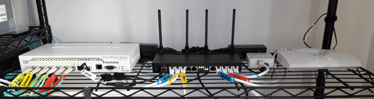
Yes, I know what your first question is. The cable labels are these ones. Write with a felt tip marker, erase with warm water.
The core of the local network needs to handle most isolation tasks (firewalls, VLANs, etc.), plus managing uplinks (fail-over, shaping traffic, etc). Therefore, we need a smart device there. In my old days, I would go and set up a spare Linux box that would do everything. In fact, some of my "lab servers" today are smaller devices that I used to run at the network core. Over the years, I have gradually replaced many Linux network boxes with Mikrotik devices.
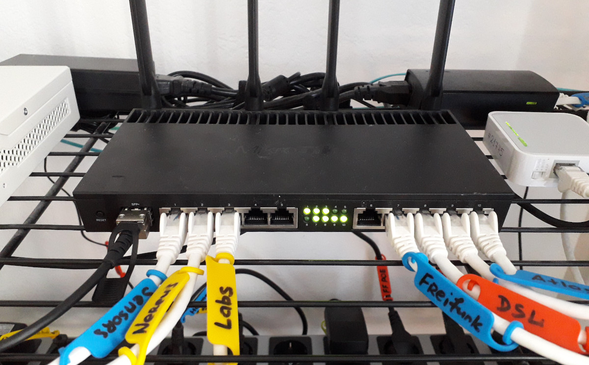
RB 4011 is overkill for most uses, and it is quite expensive. Most home networks do not need this kind of gear. My own choice was driven by several considerations: IPSec performance for tunneling between different home/VPN networks, decent amount of Ethernet ports that I can plug different-ranked devices into, the integrated wireless AP that simplifies deployment, enough CPU capacity to drive complex firewall and bridging rules without bottlenecking on router CPU.
I should say this again: Mikrotiks are not for everyone. Their powerful features come as the double-edged sword: you have to know what you are doing, or at least be ready to read a lot. In most cases, the experience with networking itself, and probably with Linux networking specifically, would come as the huge help. This is how I look at these boxes: they are Linux boxes in disguise. When it comes to doing firewall rules, you can clearly see iptables, when doing shaping rules, tc, etc.
When building the network, especially for working from home, it is important to consider what happens when one piece of the network breaks. Yes, you can technically grab a laptop and go to the nearest library until it blows over, but what if you need to survive the outage lasting full days?
In the case of network core, I have the backup hEX (RB 750 Gr3) router that used to be the old core. Its configuration closely resembles the configuration of the current core, albeit at lower Ethernet port count. So if core RB 4011 breaks, I can get a major part of my home network back just by re-plugging half of the Ethernet cables back to hEX, and rewiring the fiber links back to Ethernet.
The Uplink
Since I live in Germany, VDSL2 is still pretty much a thing, so the other part of the core is the DSL modem. I run DrayTek Vigor 165 in bridge mode, where it basically converts the DSL media to the Ethernet that core RB 4011 terminates with appropriate VLANs and PPPoE. I chose Vigor because it gives me more verbose line stats, and allows fine-tuning the SNR delta. Being able to trade in synchronization rate for better SNR margin is a nice fallback when/if DSL misbehaves.
Sample status log, negotiated at 12 dB SNR:
Vigor165> vdsl status
  ---------------------- ATU-R Info (hw: annex B, f/w: annex A/B/C) -----------
   Running Mode            :      35B       State                : SHOWTIME
   DS Actual Rate          :149747000 bps   US Actual Rate       : 43754000 bps
   DS Attainable Rate      :209420088 bps   US Attainable Rate   : 44264000 bps
   DS Path Mode            :        Fast    US Path Mode         :        Fast
   DS Interleave Depth     :        1       US Interleave Depth  :        1
   NE Current Attenuation  :       20 dB    Cur SNR Margin       :       12  dB
   DS actual PSD           :    14. 2 dB    US actual PSD        :     4. 2  dB
   NE CRC Count            :       85       FE CRC Count         :     7379
   NE ES Count             :       24       FE  ES Count         :     2740
   Xdsl Reset Times        :        0       Xdsl Link  Times     :        1
   ITU Version[0]          : 00000000       ITU Version[1]       : 00000000
   VDSL Firmware Version   : 08-0D-01-09-01-07   [with Vectoring support]
   Power Management Mode   : DSL_G997_PMS_L0
   Test Mode               : DISABLE
  -------------------------------- ATU-C Info ---------------------------------
   Far Current Attenuation :       16 dB    Far SNR Margin       :        7  dB
   CO ITU Version[0]       : xxxxxxxx       CO ITU Version[1]    : xxxxxxxx
   DSLAM CHIPSET VENDOR    : < BDCM >
It helps to diagnose wiring performance. For example, it was proven experimentally that ziptying the long unshielded DSL twisted pair cable with other cables is not a good idea, d’uh. Also, proving that DSL engineers have not screwed up the connection when moving the sockets from one room to the other by demonstrating SNR had not degraded is a nice touch.
Deep down I lament the absence of plain Ethernet or fiber connection in my apartment building. Oh well. In principle, I can go and replace the Vigor 165 device with VDSL2 SFP+ module that plugs directly into RB 4011, but that does not seem to buy me anything substantial in comparison to a separate device. That SPF+ port is better used to uplink the 10G switch.
The VDSL2 modems also have backups. The ISP’s own Fritzbox router is still usable in the same bridge mode to get the uplink running if Vigor 130 fails. ALLNet MC115 that I used before as the reliable bridge works too, but only at ADSL2+ speeds (there is a newer model that supports VDSL2 vectoring, but why bother when Vigor works). The advantage for running those modems in bridge mode is interchangeability: plug it between WAN port on RB 4011 and DSL socket, done. RB 4011 config does not care what actually translates DSL for it.
If DSL link fails altogether, one of RB 4011’s wireless interfaces is repurposed to connect to the outside Vodaphone Hotspot that gives daily/weekly/monthly vouchers for accessing the internet with decent speeds. If that fails, the same thing tethers to mobile 4G devices. The good thing to handle this on core RB 4011 is that the rest of the network does not need any reconfiguration, and can proceed as usual, albeit at lower outside bandwidth. When tethering to mobile devices, centralized traffic shaping configuration allows hard rationing for the entire fleet of devices.
The Backhaul
The network core is in the study room where most of our hardware resides. Connecting that hardware is easy: wires. Normally, you would do a Gigabit Ethernet, and that should be enough. In my updated network, most of the backhaul is fiber. We will get to that soon, but we need to consider a few other options.
The story gets interesting when you need to extend the network beyond one room. Let me get one thing very straight: for in-house connectivity, your best cost/performance bet is still Gigabit Ethernet. If I ever renovate a home/apartment, I would resist laying down laying Ethernet cables. I would lay conduits: that way, you could route either Cat6, Cat7, or fiber, depending on your needs. if you don’t have this opportunity, for example you live in the old house (like me), or in a rented apartment that does not have cable channel infrastructure and/or does not take kindly to drilling walls (like mine), or you are generally lazy (like me), then you have several options.
Option 1 (Tried and Ditched In Disgust): Wireless Mesh
First is wireless mesh. Unfortunately, having studied general physics, wireless vendor guidelines, and having deployed a few of wireless networks in weird network conditions, I am a firm wireless disbeliever. They are best effort at best. There is a German saying, "Wer Funk kennt, nimmt Kabel" — quite literally, "Those who know radio, lay cables". It might work quite well in some conditions, but it would fail horribly when the conditions change. What’s worse, those unfortunate conditions (for example, a noisy neighbor!) would happen when you both need your network, and have no time to diagnose what is happening right now.
Option 2 (Tried and Ditched In Disgust): Power-Line
The second option is Power-Line Communications (PLC).
While this is better than penetrating thick walls with 2.4/5 GHz radio signal, PLC throughput still depends on the quality of the internal wiring. If you have electric devices that leak noise back into powerline, you would start getting problems, and those problems would be maddeningly intermittent: for example, when washing machine does the particularly heavy phase of washing cycle. Oh, and that also includes your neighbors. Plus, the 230V power conduits are not twisted pairs, so they naturally take on noise.
In practice, PLC works somewhat well. I have been running with the network is backhauled with PLC adapters, with about 5 adapters in the network. Over time, you start to feel the problems with PLC. One problematic thing is latency:
$ sudo ping ... -c 10000 -f

--- $core-router-ip ping statistics ---
10000 packets transmitted, 10000 received, 0% packet loss, time 1319ms
rtt min/avg/max/mdev = 0.075/0.125/0.191/0.015 ms, ipg/ewma 0.131/0.129 ms

--- $over-plc-1 ping statistics ---
10000 packets transmitted, 10000 received, 0% packet loss, time 45221ms
rtt min/avg/max/mdev = 1.365/4.506/20.787/1.762 ms, pipe 2, ipg/ewma 4.522/4.773 ms

--- $over-plc-2 ping statistics ---
10000 packets transmitted, 10000 received, 0% packet loss, time 31883ms
rtt min/avg/max/mdev = 1.343/3.188/41.067/2.050 ms, pipe 3, ipg/ewma 3.188/3.829 ms

--- $over-plc-3 ping statistics ---
10000 packets transmitted, 10000 received, 0% packet loss, time 48889ms
rtt min/avg/max/mdev = 2.201/4.935/133.664/3.304 ms, pipe 9, ipg/ewma 4.889/8.132 ms

--- $over-plc-4 ping statistics ---
10000 packets transmitted, 10000 received, 0% packet loss, time 63420ms
rtt min/avg/max/mdev = 1.390/6.429/43.853/3.196 ms, pipe 3, ipg/ewma 6.342/6.458 ms
The first host is connected via the Ethernet. All others are connected via PLC bridges. As you can see, PLC bridges add at least 1 ms latency, 3..6 ms on average, with outliers of up to 130 ms. While this works for most workloads at my home, these numbers are not something to be proud of.
The other problematic thing is throughput. In my measurements it is fairly consistent: between two pair of sockets, it is either consistently good or consistently bad. It sometimes happens that the different sockets on the same wall are performing very differently, because they are being wired through the different circuits. Point-to-point bandwidth measurements (another plus for Mikrotik devices is bundled bandwidth testing tools) shows that realistic throughputs of about 30..80 Mbps are achievable with PLC. This is a far cry from the advertised 1300 Mbps speeds, but still better than nothing. Yes, 1300 Mbps is max PHY speed, but it is ridicolous to only get a few percents of that speed for the payload.
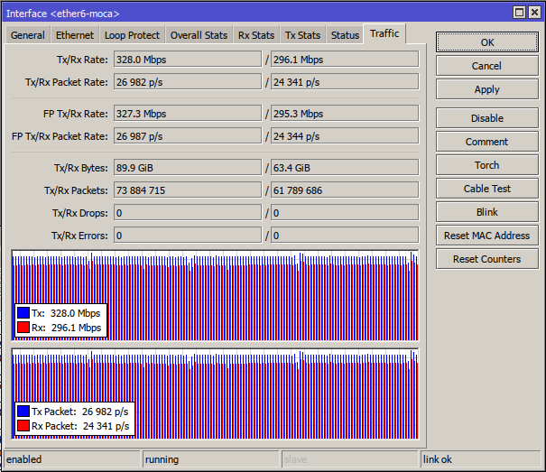
Option 3 (Tried and Retired With Honors): Multimedia-over-Coax (MoCA)
There is a third option available in apartments like mine, MoCA, networking over coaxial cable. In my German apartment, there is no Ethernet, but there is TV coax cable routed to every room! So it is possible to bridge Ethernet over it. My old network used Hirchmann INCA 1G adapters for this:
The improvements in latency are apparent:
$ sudo ping ... -c 10000 -f

--- $core-router-ip ping statistics ---
<still on Ethernet, see the result above>

--- $over-moca-1 ping statistics ---
10000 packets transmitted, 10000 received, 0% packet loss, time 40018ms
rtt min/avg/max/mdev = 3.555/3.987/11.971/0.115 ms, ipg/ewma 4.002/3.976 ms

--- $over-moca-2 ping statistics ---
10000 packets transmitted, 10000 received, 0% packet loss, time 40063ms
rtt min/avg/max/mdev = 3.531/3.991/13.995/0.241 ms, pipe 2, ipg/ewma 4.006/3.988 ms

--- $over-moca-3 ping statistics ---
10000 packets transmitted, 10000 received, 0% packet loss, time 40064ms
rtt min/avg/max/mdev = 3.556/3.988/13.996/0.240 ms, ipg/ewma 4.006/3.981 ms
The latency is consistently above 3.5 ms and near 4 ms, which seems to be in line with the MoCA 2.0 performance targets. The impressive thing is that latency numbers are not spread far away. All three targets have nearly the same characteristics: minimum and average latencies, test time are the same. This goes in stark contrast with PLC.
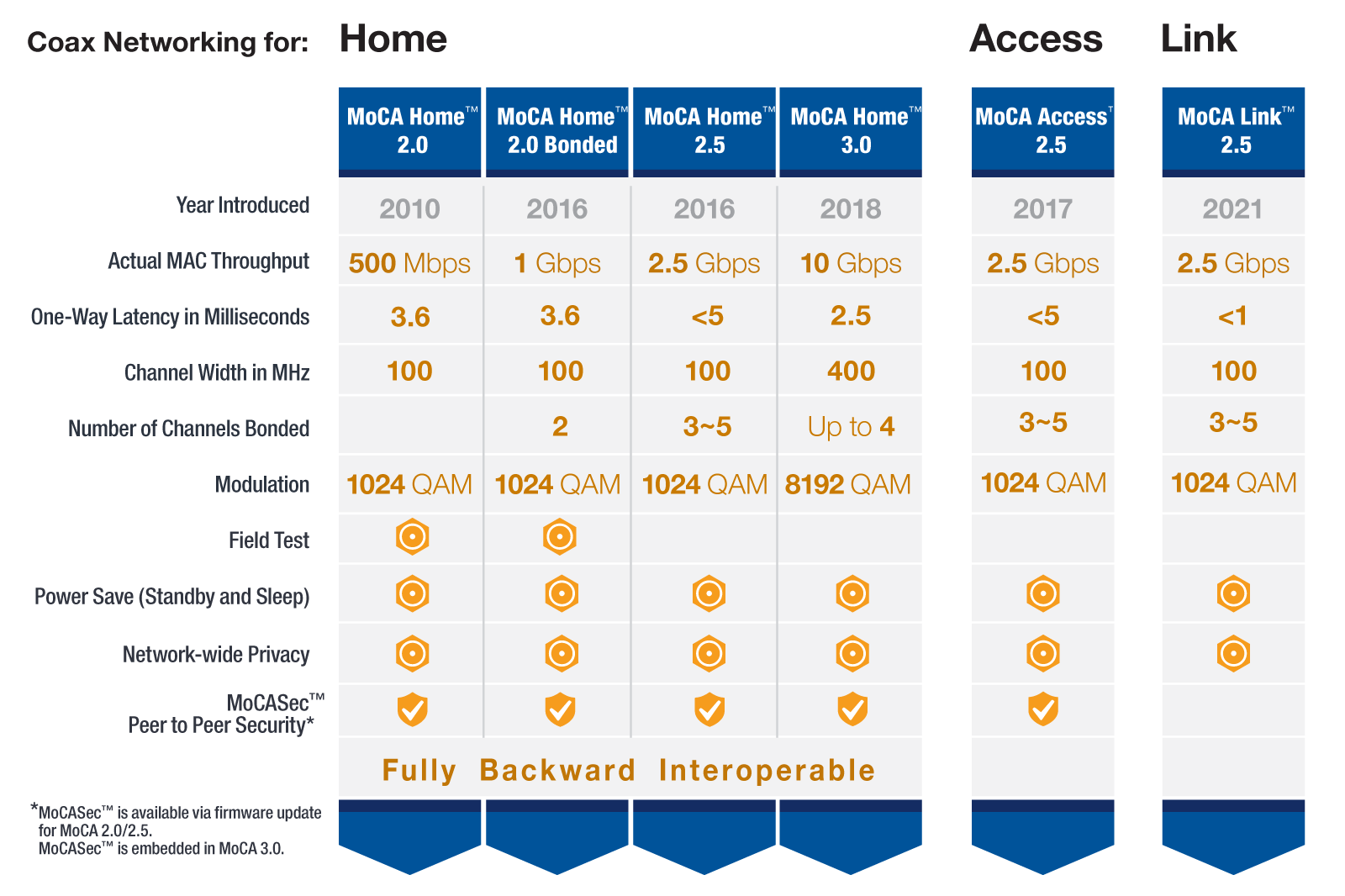
The throughput figures are also good: the point-to-point tests show about 850+ Mbps for the entire network, the order of magnitude improvement over PLC. With older 100 Mbps ports on access switches, MoCA fully saturates all Ethernet ports with all-out duplex test.
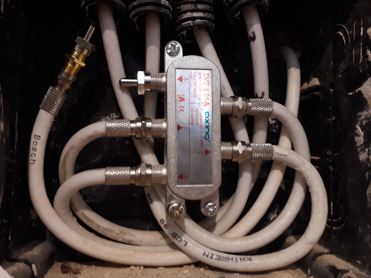
While MoCA is designed to coexist with CATV, it seems to run best over the "dark coax": the coax cable that does not carry anything else. Running my MoCA adapters on non-dark coax cuts the bandwidth in half, probably because noise gets much worse. Going fully dark also improves security, as MoCA signal does not leave the apartment. At least for INCA 1G adapters, there is no way to re-key the network encryption, so isolation is definitely needed. There are MoCA PoE (point-of-entry) filters that can filter MoCA frequency bands without disconnecting the input cable.
The splitter itself should also have enough bandwidth to pass MoCA (INCA 1G uses Band D, which goes up to 1675 MHz). The caveat with many splitters is port isolation: there is >20 dB loss between the output ports. My MoCA network works even with that kind of loss, but why not optimize it a little? MoCA best practices recommend to mitigate this by putting the MoCA PoE filter at the input port even without the uplink connected. This is counter-intuitive, until you realize the output port signal can reflect off that filter to reach another output port, which would take twice the input-output loss, about 2*(3..7) dB, depending on how many ports your splitter has.
That said, I run my splitter the unusual way. The network is used asymmetrically, with core router pushing lots of traffic to access routers, but the access routers themselves are not talking with each other much. Putting the core router coax into the input port gets ~7 dB insertion loss on important link pairs, and about 150 Mbps of additional throughput on my longest coax run.
Putting the proper terminator caps on free/dangling coax is recommended to avoid unnecessary reflections due to mismatched impedance.
Again, backup question. The backhaul is not that important in the grand scheme of things, because it does not affect our daily work. That said, it would still be inconvenient to have home network degraded. With both MoCA and PLC, the adapters are pretty much interchangeable, so if one node fails, we can replace it with another one. If there are no hot spares, we can rebalance the adapters across the apartment to get more important spots the connectivity first.
This option is nearly perfect as far as the balance in construction costs and expected performance goes. The next step is something for my geek pleasure. Still, the MoCA stuff is good enough to remain in this writeup as the warm keepsake.
Option 4. Multi-Mode Optical Fiber
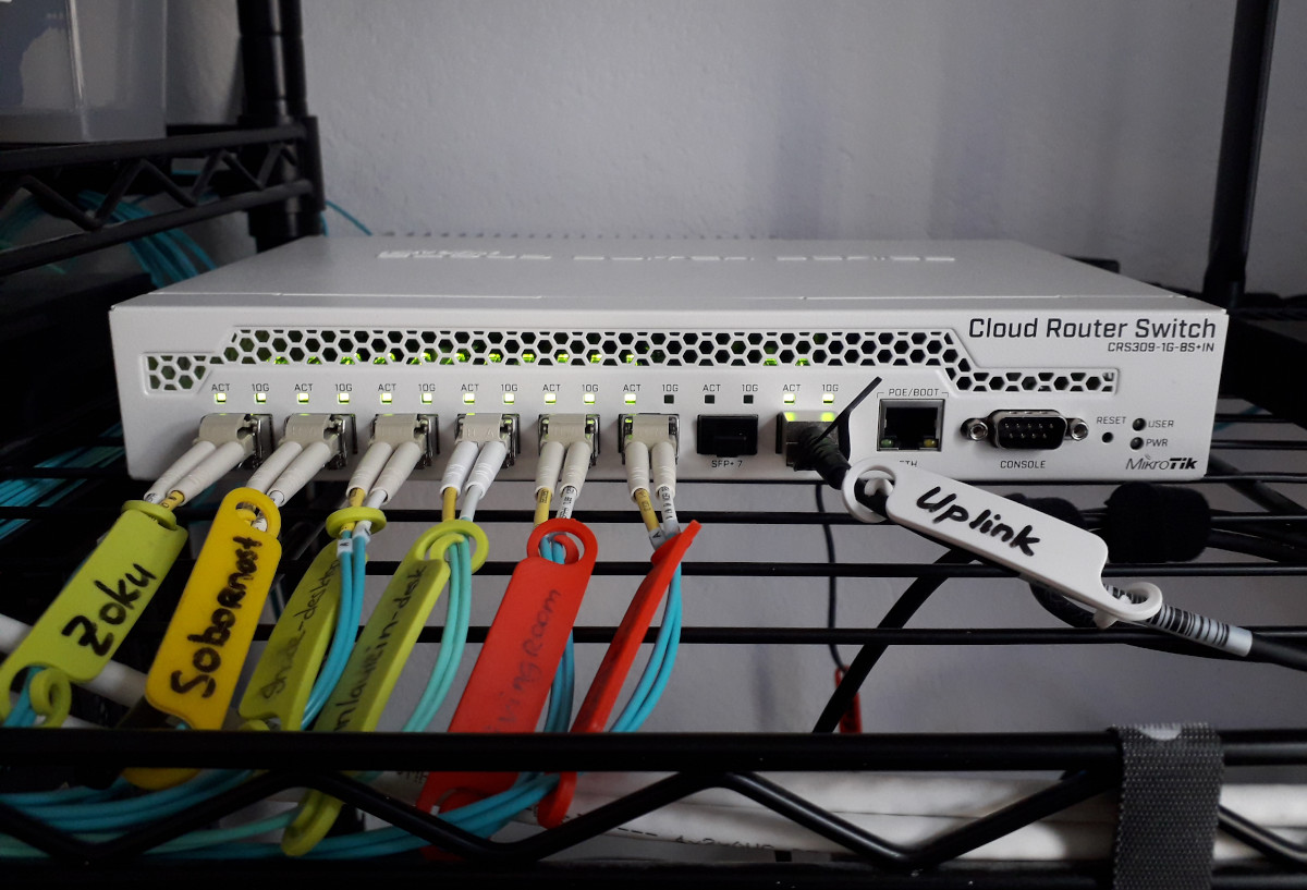
At this point, the ultimate upgrade for the modern home network is 10G. The switch above is the core switch that handles the core 10G network, connecting file server, our desktops, and lab servers. Those machines are hooked straight to CRS-309 with fiber. Some of those machines could technically use copper Direct Attach Cables (DAC)s, but I found that fiber is much easier to work with: the cables are thinner, softer, more forgiving. Plus, you can (and you probably) always will have the spare fiber near the ports, in case you ever move machines and/or routers.
The choice of OM3 multi-mode fiber is not accidental: it seems to hit the sweet spot in both fiber and transceiver prices, while giving the headroom for up to 100G on household distances. I highly recommend pre-terminated fiber patch cords from FS.
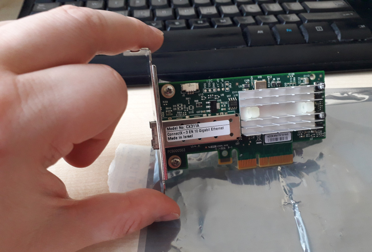
Since machines do not have fiber ports on their mainboards, they carry Mellanox ConnectX-3 cards to fit the SFP+ transceivers:
Coincidentally, fiber can be used for the longer backhaul. The long pre-terminated fiber patch cords are actually a pleasure to work with: the cable is very thin (2 mm), very malleable, and accepts small bending radius (7.5mm for my cable). It is definitely an improvement over quite rigid Cat7 cable. The only "problem" is fiber color coding. For my OM3 fiber cable, the default jacket color is aqua, which makes it clearly visible against the white walls. This can be mitigated by covering them with white tape (to be done here).
So, one of the CRS-309 ports is actually the uplink for the to distribution switch in other room:
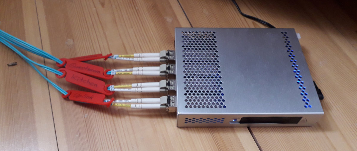
This is where fiber is again very handy: I can route a single OM3 cable and carry the entire 10G trunk for all those APs. If/when it would need a bandwidth bump, the same cable could carry up to 100G. Hopefully, the only thing that would need upgrade are transceivers.
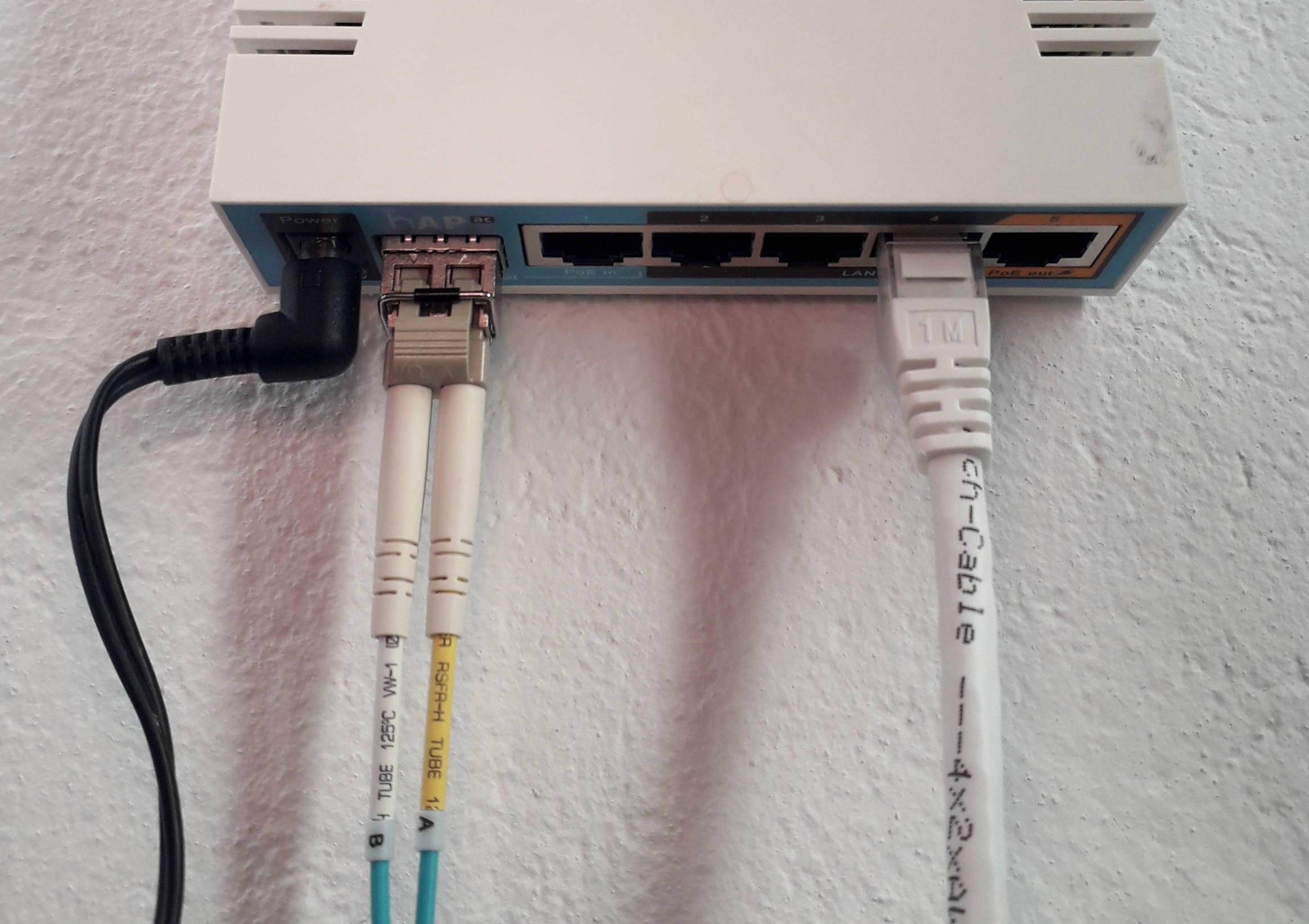
The Access
At this point, we have built the core and the backhaul. Now we have to terminate the backhaul with the actual access points. Those access points have to do both Ethernet and wireless. PLC gives about 100 Mbps in good conditions here, so getting the access routers with Gigabit ports might be a bit of overkill. With MoCA, you might want to terminate with Gigabit, but then you would not like to overload the MoCA network. With fiber, you can pretty much do whatever, either SFP or SFP+ uplinks. You would also like to have an access point per room, which means the routers should not be very expensive.
Therefore, in my network the access points are Mikrotik hAP AC-s, bought on second-hand market for peanuts.
Wireless Power
I think the most ubiquitous mistake in wireless deployments is trying cover the entire area with a single powerful wireless Access Point (AP). This runs into a bunch of problems:
-
The AP itself can transmit on high power (i.e. some Mikrotiks are able to pump out 30 dBm (1 W) of power!), and client would hear the AP, but the client transponder is not powerful enough to pass through the same path back to AP. It is somewhat mitigated by advanced APs having the much more sensitive receivers, and that might take you quite far.[1]
-
The default 802.11 clients use CSMA/CD to coordinate (hah) the media access. "CD" means the clients listen if the air is clear to transmit. This works fine, until two clients cannot see each other, but still can see the AP. Since one client cannot sense the other client is currently transmitting, the collision detection breaks. This is known as "hidden node problem". It can be mitigated by RTS/CTS, but that increases the wireless overhead dramatically.
-
Placing a single AP gets funky if we want to have coverage in every corner, especially given non-line-of-sight transmissions, multi-path interference, cosine losses, etc. Moving the AP 10 cm in one direction can open or close the path to some corner of the far-away room. Been there. This hi-tech feng shui gets tedious real fast. [2]
It is much easier to have the line-of-sight AP near the client. (I see the value in ceiling-mounted APs!) Therefore, access routers are in almost every room. Once we have most clients always near the AP, we can trim down the AP power to make the nearest ones easily discoverable, while others being naturally below the noise threshold.
In my network, all wireless APs are at low power, 10..11 dBm (10..13 mW) each. With antenna gain of 2..3 dBi, it gives 12..14 dBm, or 16..25 mW of transmit power. This is well below the standard 20 dBm (100 mW), and all of them together radiate as much energy as one default wireless router. But a really, really distributed one.
Wireless Frequencies
All Mikrotik routers are dual-band capable, so they service both 2.4 GHz and 5 GHz networks. There are surprisingly many clients that can do 2.4 GHz only: wireless printer, low-end smartphones, some sensor devices, etc.
The goal for wireless deployment is not raw throughput, but reliability. Therefore, the frequency plan uses a number of non-overlapping small channels. The 2.4 GHz network is deployed on usual channels {1, 6, 11} — the group of non-overlapping 20 MHz channels:
/interface wireless channels
add band=2ghz-b/g/n frequency=2412 list=wlan name=2ghz-ch1 width=20
add band=2ghz-b/g/n frequency=2437 list=wlan name=2ghz-ch6 width=20
add band=2ghz-b/g/n frequency=2462 list=wlan name=2ghz-ch11 width=20
The 5 GHz network is more complicated, because the regulatory rules are complex there. The set of non-overlapping 40 MHz channels in my network are on channels 36..54:
/interface wireless channels
add band=5ghz-onlyac extension-channel=Ce frequency=5180 list=wlan name=5ghz-ch36/38 width=20
add band=5ghz-onlyac extension-channel=Ce frequency=5200 list=wlan name=5ghz-ch40/42 width=20
add band=5ghz-onlyac extension-channel=Ce frequency=5220 list=wlan name=5ghz-ch44/46 width=20
add band=5ghz-onlyac extension-channel=Ce frequency=5240 list=wlan name=5ghz-ch48/50 width=20
add band=5ghz-onlyac extension-channel=Ce frequency=5260 list=wlan name=5ghz-ch52/54 width=20
The first three do not require DFS (radar detect) capabilities, and so start up nearly instantaneously. The last two are in DFS regulation spectrum, so radar detection takes a while. 40 MHz wide channel is enough to pull 1-stream 200 Mbps, which is more than enough given the available uplink bandwidth on access routers.
Wireless RSSI Cutoffs
Wireless roaming is about switching to best AP with the same SSID. The basic problem is that both access points and clients do not have any idea about their relative positions or their surroundings. The only reasonable proxy they have is the signal strength. The decision to roam is usually driven by the clients. That is, the wireless clients themselves decide which access point to use among all APs visible for a given SSID.
Therefore, it might happen that a client associates with the "closest", actually more powerful access point, then the client moves near another access point, and… nothing happens, as client maintains the association with that far AP. While there are ways for client to listen actively for better APs, it leaves us to the mercy of proper client implementation. It is more convenient to let APs act themselves.
Since APs also know about the signal strengths, we can configure them to boot the clients that fall below the signal strength threshold, thus forcing them to look for another AP with the same SSID. In Mikrotik speak, that amounts to doing the access list:
/interface wireless access-list
add interface=${wlan-interface} signal-range=-70..120
When the signal to the client falls out of the signal-range, the AP decides that the client no longer satisfies the access criteria and asks the client to leave. While crude, this works surprisingly well. As we have an AP in each room, walking from one room to another gets the client booted from bad APs to better ones. This roaming is not exactly seamless, because while client re-associates with another AP it has packets queued up, but it works decently well in practice. If you want the actual seamless roaming, you need to look into 802.11r.
This needs to be configured on every access point, unless you do CAPsMAN. I don’t do CAPsMAN, because I also want to fine-tune the access routers individually.
Wireless Ping Cutoffs
Another way make backhaul more bullet-proof is to detect the connectivity problems early. For that reason, the access routers actively ping the core router, and if those pings are going bad, then the access router shuts down its wireless networks for a while, until pings stabilize. Since there are adjacent APs in sight, this is usually transparent for clients. This solves the problem when you have the physical wireless connection, but no traffic goes through. For example, when you accidentally screw up the backhaul configuration, or backhaul routers restart, or you need to do some wiring work.
In Mikrotik speak, that amounts to running the special periodic script like this:
:if ([/ping $core-router-ip interval=0.2 count=5] = 0) do={
  :if ([/interface get $intf_1 disabled] = no) do={
    :log error "Connectivity problem, disable wireless"
    /interface disable $intf_1
    /interface disable $intf_2
    :sleep 60
  }
} else {
  :if ([/interface get $intf_1 disabled] = yes) do={
    :log info "Connectivity problem resolved, enable wireless"
    /interface enable $intf_1
    /interface enable $intf_2
  }
}
Wired Ports
The good thing about having access routers is their Ethernet ports. Connecting to wired port instead of wireless sometimes makes sense. For example, when pulling a lot of data through the network while keeping the wireless free for others.
The other real use case is connecting hardware, like sensor boxes and 3rd party routers. It helps to have the PoE ports for this as well! Example devices running off Mikrotik’s PoE ports:
-
Two Freifunk nodes using TP-Link CPE 210 routers. They are powered from the PoE ports on the nearest access routers.
-
Several sensor boxes using the RPi Zero and Ethernet Shields. They are also powered from PoE ports on the nearest router, but through the 24V→5V step-down converter.
This also gives the natural way for these devices to be aggregated and carried to core router with VLANs. More about that below.
Service Overlap
Access routers overlap their service areas, so one of them going down degrades the network a bit, but the connectivity is still there. Even with half of them failing, the network coverage remains quite decent. If more are failing, the access routers are interchangeable, so we can physically reshuffle them around the apartment, and no further reconfiguration is needed.
Network Layer (Subnetworks)
Now we have built the physical layer for the network, it is time to build the network layer on top.
Since we have multiple ranks of clients, the natural way to segregate them is to give each of those their own /24 subnetwork. To simplify routing, we can just carry each of those networks on their own VLAN, let the core router aggregate them in bridges, and do all the firewalling there. This makes the access router configuration simple: just bridge the relevant ports to relevant VLANs, and done.
Separate /24 subnetworks also means that clients have to go to core router for forwarding, and there is no way the accidental routing mistake on one of the access routers would circumvent the global routing policy.
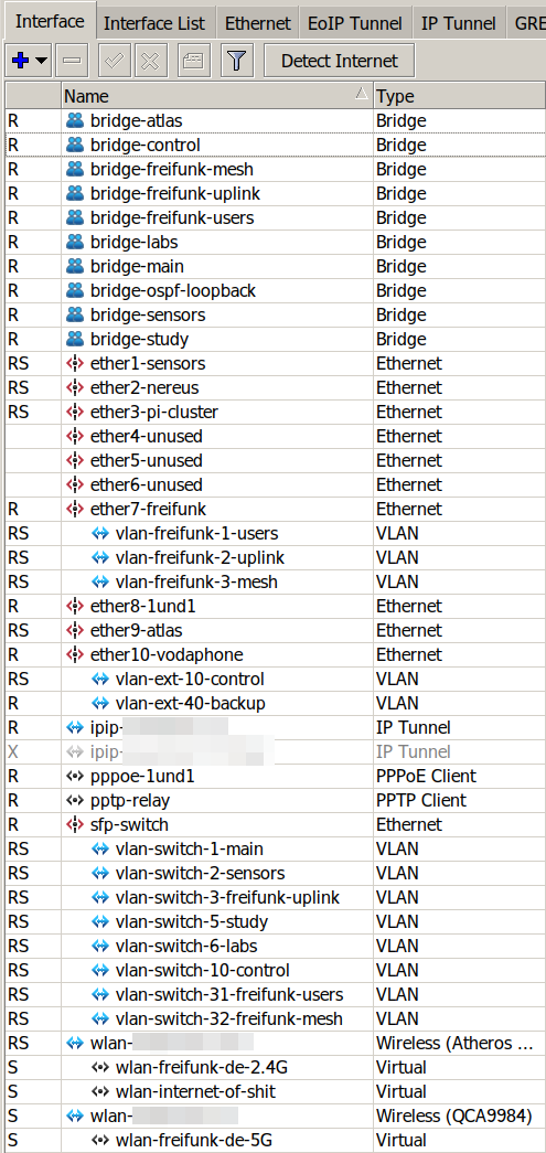
The only wrinkle in the whole scheme is the tight cohesion between CRS-309 and RB 4011. CRS switch is configured as dumb L2 switch with VLAN trunk port attached to RB 4011 (sfp-switch on the picture on the left). This effectively means than the inter-VLAN traffic between different subnetworks have to "loop through" RB 4011, even if both parties are on adjacent SFP+ ports in CRS-309. In practice, this works quite well: with fast-tracking on RB 4011, a single TCP stream of 5 Gbps maxes out one of four RB 4011 cores. With two TCP streams, we max out the entire 10G link.
Study Subnetwork
The most privileged network is the study network that runs our work computers. Those can access almost all devices on all other subnetworks, but the reverse is not true. This subnetwork is not even carried by wireless, so if I wanted to have the same privilege level as my desktop on my laptop, I need to physically plug it in.
Main Subnetwork
Main subnetwork is what most deployments have as the only network: it handles the normal devices, and it is a default subnetwork for wireless users and Ethernet ports on access routers. These can access Internet and all other same-rank devices, but not much else. Which means that even if you know the WiFi password or you plug into Ethernet in other rooms, you are not able to access the sensitive parts of the network.
Labs Subnetwork
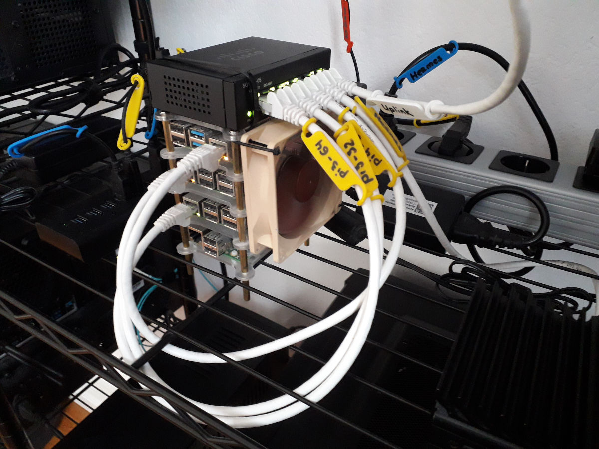
When running lab servers that carry experimental hardware and software, firewalling them individually is not convenient. This is doubly so for virtual machines that run on lab server. Because of this, the entire lab subnetwork is isolated, and the bulk of smaller Pi hosts are carried by its own separate switch.
The access to lab subnetwork is possible from a selected few devices, mostly our work machines.
The lab network also has no access to Internet, apart from a few designated version control hosts that they routinely communicate with (for example, hg.openjdk.java.net). So, the lab servers would not be able to auto-update, or push telemetry, or do something else that might in-/ex-filtrate the sensitive data. When build servers need to push the builds, they don’t even go to Internet, but rather push them to a designated file server that mirrors it to Internet (say, builds.shipilev.net) in one go.
Once updates are needed, I can selectively enable the firewall rule that allows lab servers to go outside, update them in a batch, and then disable the rule back.
Sensors Subnetwork
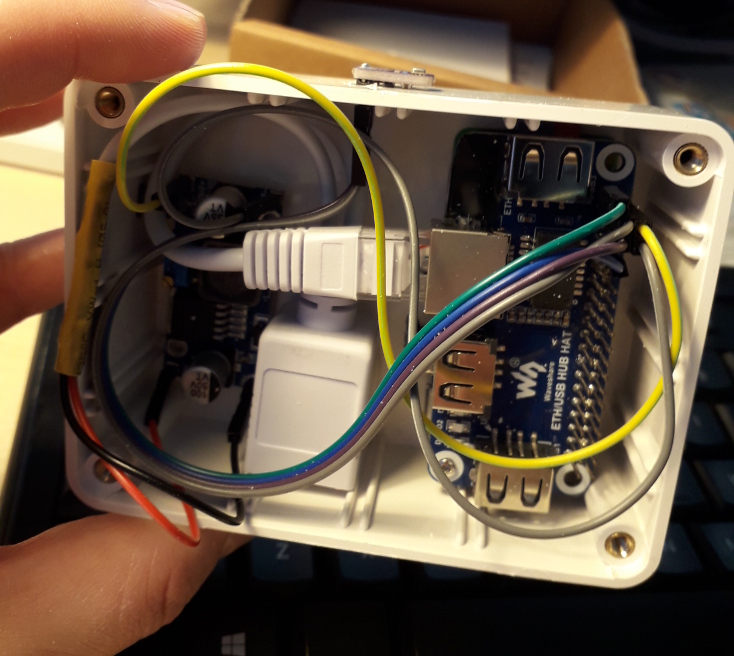
Sensors run a number of Pi Zero nodes powered by PoE via 24-5V stepdown converters. These sensors run the seldom-updated Linux distros, sometimes they run software that was written by some unknown IoT enthusiasts. And generically, I don’t want them in the main network, so they get their own.
The sensors subnetwork does not have access to anything beyond a particular internal host/port where they feed the data to. Connecting to sensors is allowed from the set of designated hosts as well. Overall, this is the most fortified subnetwork here: completely untrustworthy in both directions.
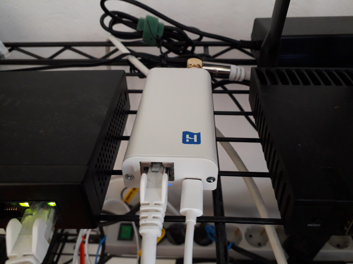
RIPE Atlas Subnetwork
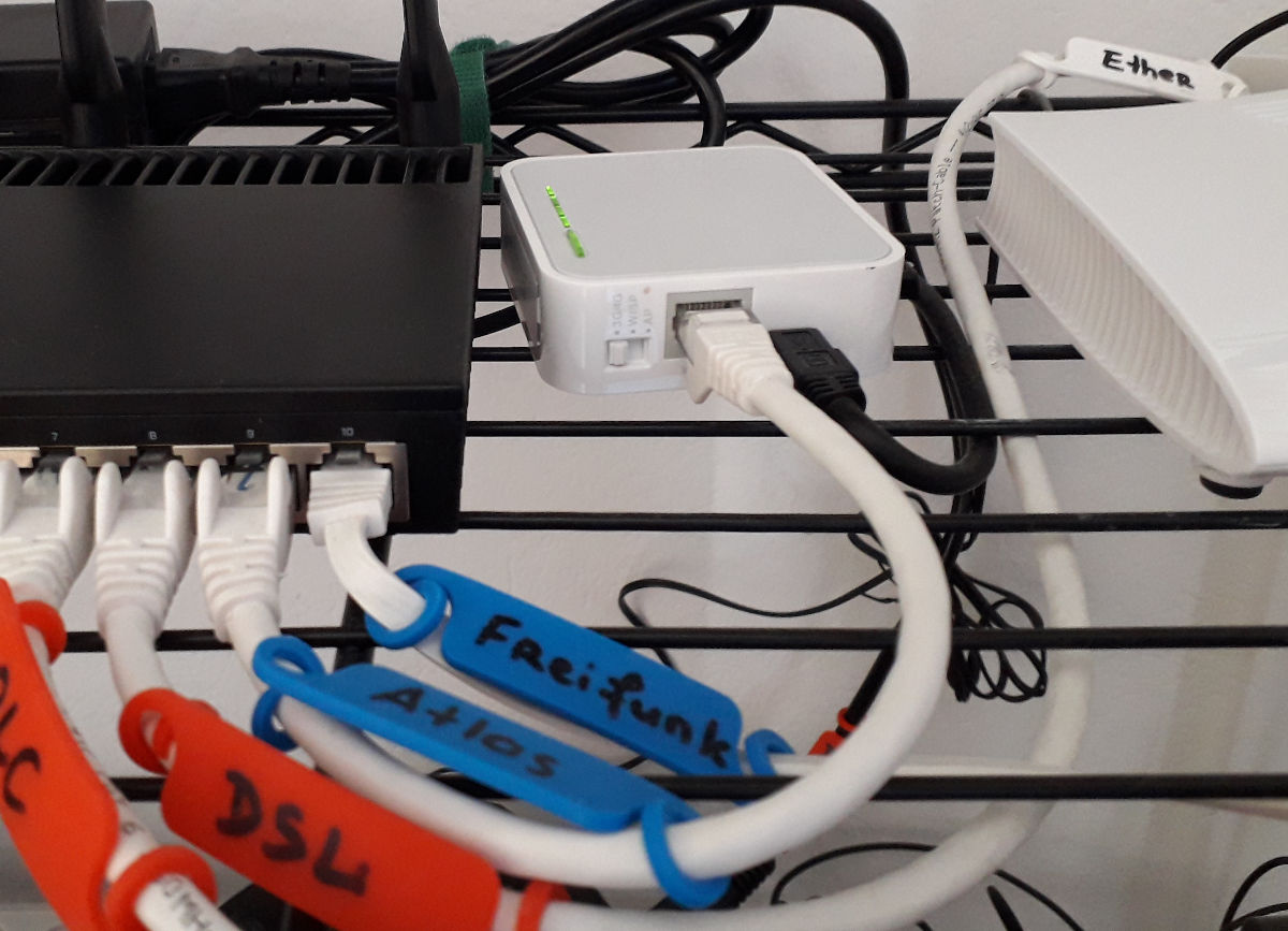
Another special device in the network is the RIPE Atlas probe node.
While RIPE people get my respect and trust with configuring their nodes correctly, that is still 3rd-party node running within the home network, and it can in principle be used as the intermediate node to get into the home network. It also auto-updates itself, so there is however small possibility of receiving the malicious code drop. Therefore, while this probe naturally has access to Internet, it is firewalled hard from the rest of any network.
On the upside, it can be routed through different uplinks, depending on which AS has lesser density of probes (ask RIPE Atlas folks for guidance here).
Freifunk Subnetwork
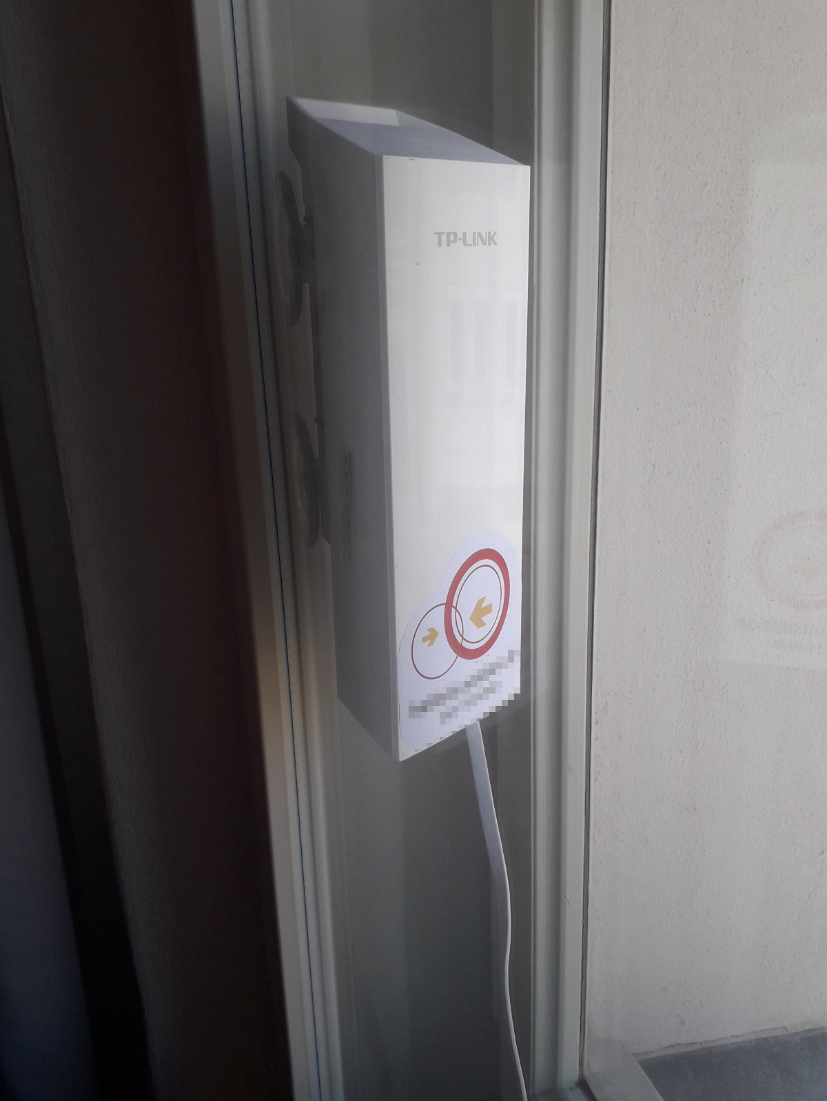
As I mentioned before, two Freifunk nodes are using TP-Link CPE 210 routers.
Freifunk VLANs are numerous, because they are carrying different layers of the network data.
For starters, there is "freifunk-uplink" VLAN that is used by both nodes to access the Internet. They are terminated at the core router and both nodes share their own /24 subnetwork. Firewalls isolate the routing from that network towards the rest of the subnetworks, plus only allow Internet exiting towards the Freifunk VPN servers and a handful of monitoring hosts. This provides the additional layer of security in case the botched configurations on FF nodes would start leaking the traffic from the unauthenticated users via my uplink.
Then, there is "freifunk-users" VLAN that carries Freifunk users. Normally, FF users connect directly to Freifunk nodes, but that "freifunk-users" VLAN also allows me to carry Freifunk services on every other access router in my home. So, when someone connects to one of the access routers with freifunk SSIDs, it would be carried via that VLAN to the destination Freifunk node, that would route it as if it was (it actually is) the regular Freifunk user.
Then, there is "freifunk-mesh" VLAN that allows Freifunk nodes to mesh together through the local Ethernet network. The Freifunk network itself runs the OLSR, and it is technically possible to tell the nodes to discover themselves over the Ethernet. In practice, that means if one node’s uplink is down, then it would redirect the traffic through the mesh to another node. And, in the city-wide mesh network, it provides one of the repeater bridges: one CPE210 looks one way, meshes with another CPE210, which looks the other way.
Network Layer (Services)
Traffic Shaping
The core router also shapes the network traffic. This is rarely important for internal traffic, because internal network bandwidth is quite abundant, but it is important for rationing the uplink. It is easy to classify the traffic with a few simple rules. For performance reasons, we would like to leverage connection tracking for this.
So, first mark all new connections with connection marks:
/ip firewall mangle
add action=mark-connection chain=prerouting connection-state=new \
  in-interface=bridge-freifunk-uplink new-connection-mark=priority-freifunk passthrough=no
add action=mark-connection chain=prerouting connection-state=new \
  protocol=tcp dst-port=80,81,443,8080,8081 new-connection-mark=priority-normal passthrough=no
add action=mark-connection chain=prerouting connection-state=new \
  protocol=tcp dst-port=22,3389,8291 new-connection-mark=priority-high passthrough=no
Then translate connection marks to packet marks for every packet — this saves more complicated match against the port sets, etc:
/ip firewall mangle
add action=mark-packet chain=forward connection-mark=priority-normal \
  new-packet-mark=priority-normal passthrough=no
add action=mark-packet chain=forward connection-mark=priority-high \
  new-packet-mark=priority-high passthrough=no
add action=mark-packet chain=forward connection-mark=priority-freifunk \
  new-packet-mark=priority-freifunk passthrough=no
add action=mark-packet chain=forward \
  new-packet-mark=priority-background passthrough=no
Then use Mikrotik’s simple queues to chop up the downlink/uplink:
/queue type
add kind=pcq name=pcq-download pcq-classifier=dst-address,dst-port
add kind=pcq name=pcq-upload   pcq-classifier=src-address,src-port

/queue simple
add dst=$uplink name=internet-high packet-marks=priority-high \
  limit-at=20M/50M max-limit=35M/80M queue=pcq-upload/pcq-download
add dst=$uplink name=internet-normal packet-marks=priority-normal \
  limit-at=15M/20M max-limit=35M/80M priority=5/5 queue=pcq-upload/pcq-download
add dst=$uplink name=internet-background packet-marks=priority-background \
  limit-at=5M/10M  max-limit=35M/80M priority=2/2 queue=pcq-upload/pcq-download
add dst=$uplink name=internet-freifunk packet-marks=priority-freifunk \
  limit-at=30M/30M max-limit=30M/30M priority=1/1 queue=pcq-download/pcq-upload
add dst=$uplink name=internet-nomark packet-marks=no-mark \
  limit-at=5M/5M   max-limit=35M/80M queue=pcq-upload/pcq-download
With this, interactive traffic gets prioritized first, then "usual" web traffic gets the slice, then lab servers get a part, then Freifunk users pick up what is left.
It is useful to throttle some subnetworks too, so that no automated system can saturate the network:
/queue simple
add dst=$bridge-labs    name=labs    max-limit=800M/800M \
  priority=3/3 queue=pcq-upload/pcq-download
add dst=$bridge-sensors name=sensors max-limit=10M/10M \
  queue=pcq-upload/pcq-download
add dst=$bridge-atlas   name=atlas   max-limit=5M/5M \
  queue=pcq-upload/pcq-download
This shaping thing becomes very important when ISP uplink fails. Then, after tethering to external hotspot or 4G, we can trim down the limits in the shaper to ration the bandwidth correctly.
Or, as it proved useful recently, cap the labs Internet traffic when you are delivering the online talk.
DNS: Local Names and Adblock
The usual thing is local DNS forwarder to optimize DNS lookups. It also comes with two nifty opportunities.
First, it allows naming the local network nodes without maintaining the separate DNS server or messing with public DNS zones:
> /ip dns static print where name ~ ".*.shipilev.net"
 NAME                            TYPE     ADDRESS
 rpi4-arm32.labs.shipilev.net    A        192.168.xx.xx
 rpi3-arm64.labs.shipilev.net    A        192.168.xx.xx
 rpi3-arm32.labs.shipilev.net    A        192.168.xx.xx
 main.freifunk.shipilev.net      A        192.168.xx.xx
 kitchen.routers.shipilev.net    A        192.168.xx.xx
$ ping rpi3-arm64.labs.shipilev.net
PING rpi3-arm64.labs.shipilev.net (192.168.xx.xx) 56(84) bytes of data.
64 bytes from rpi3-arm64.labs.shipilev.net (192.168.xx.xx): icmp_seq=1 ttl=63 time=0.738 msSecond, it allows a crude Adblock by resolving offending hosts to a private IP:
> /ip dns static print
 NAME                 TYPE     ADDRESS
 static.a-ads.com     A        240.0.0.1
look-at-my-ads.com A 240.0.0.1…and then rejecting the connection to it:
/ip firewall filter
add action=reject chain=forward comment=Adblock dst-address=240.0.0.1 \
  reject-with=icmp-host-prohibited
The benefit of doing that on the core router is implicitly covering every device in the managed network.
NTP: RTC Bootstraps
One of the understandable but still surprising things about Pi Zero is the absence of always-on real-time clock. This means when my sensor node starts up and tries to submit the sensor data, it is rather confused about the current time. The way out is to sync the time with NTP at startup. But since sensor nodes are prohibited from exiting to Internet, they need the local NTP.
Cost Estimates
I started several years ago, with a basic list with PLC adapters and weaker routers:
 100 EUR: 1x Mikrotik hAP AC
 120 EUR: 3x Mikrotik hAP AC lite
  40 EUR: 1x Cisco SG110D-08-EU
  80 EUR: 4x TP-Link TP-7010 (second-hand)
   0 EUR: 1x Fritzbox (ISP-given)
  20 EUR: assorted cabling
 ..........................
360 EUR: <total materials>…then MoCA-based network added up to:
 200 EUR: 1x Mikrotik RB 4011
 160 EUR: 4x Mikrotik hAP AC lite
 260 EUR: 4x Hirschmann INCA 1G
  40 EUR: 1x Cisco SG110D-08-EU
 100 EUR: 1x Draytek Vigor130
  40 EUR: 1x TP-Link CPE210
  40 EUR: 2x TP-Link TP-7010 (second-hand)
  60 EUR: assorted cabling
 ..........................
 900 EUR: <total materials>
 AAA EUR: <time spent playing with it>
 ..........................
OMG EUR: <total>…then 10G gear came in:
  200 EUR:  1x Mikrotik RB 4011
  250 EUR:  1x Mikrotik CRS 309
  140 EUR:  1x Mikrotik CRS 305 (second-hand)
  180 EUR:  4x Mikrotik hAP AC (second-hand)
  280 EUR:  4x Mellanox ConnectX-3 (second-hand)
  200 EUR: 10x FS SFP-10GSR-85 transceivers
   80 EUR:  8x FS SFP-1G-SX-85 transceivers
   30 EUR:  1x Cisco SG110D-05-EU
  100 EUR:  1x Draytek Vigor165
   40 EUR:  1x TP-Link CPE210
  100 EUR: assorted cabling
 ..........................
 1600 EUR: <total materials>
  AAA EUR: <time spent playing with it>
 ..........................
  OMG EUR: <total>
The leftovers from previous iterations are not counted here, as they would be sold eventually. As you can see, it can go up as crazy as you want. Not the most expensive of my hobbies (coughastronomycough), and is quite fun.